Whether someone is planning to power a tiny house, a cabin off grid, a camper van, or a full residential solar system, getting the wiring right is the single most important step. A clear, well-thought-out solar panel wiring diagram saves time, protects equipment, and keeps everyone safe.
This guide walks through everything a beginner needs to know — from a simple solar panel wiring diagram for beginners all the way to more advanced photovoltaic wiring diagrams for larger off-grid and grid-tied setups. Every section is written with clarity in mind, because solar wiring doesn't need to feel complicated.
Comprehensive Article Outline
| # | Section Heading | Key Topics Covered |
|---|---|---|
| 1 | What Is a Solar Panel Wiring Diagram? | Definition, purpose, types of diagrams |
| 2 | Why Every Solar Setup Needs a Wiring Diagram | Benefits, planning, documentation |
| 3 | Core Components in Any Solar Circuit Setup | Panels, controllers, batteries, inverters, fuses |
| 4 | Series vs. Parallel: Two Solar Wiring Configurations | Voltage, current, configuration comparison |
| 5 | Wiring 2 Panels in Series & Parallel | Step-by-step diagrams explained |
| 6 | 12V / 24V / 48V System Wiring Diagrams | Voltage tiers, battery bank setup |
| 7 | Off-Grid Solar Wiring: Shed to Cabin to Tiny House | Practical setups, sizing, components |
| 8 | RV, Camper Van, and Marine Solar Wiring | Mobile setups, space constraints, marine grade |
| 9 | Charge Controller Wiring: MPPT vs PWM | Connection sequence, controller selection |
| 10 | Battery Bank Wiring & Lithium Battery Setup | Equal-length cables, BMS, LiFePO4 |
| 11 | Hybrid & Grid-Tie Solar System Wiring | Net metering, hybrid inverters, grid connection |
| 12 | Rooftop Solar Installation & Residential Systems | Site assessment, racking, permits |
| 13 | Solar Cable Size Calculator & Wire Gauge Chart | AWG sizing, voltage drop, current calculations |
| 14 | Solar Safety Guidelines & Maintenance | DC hazards, monthly/annual maintenance tasks |
| 15 | Final Summary & Key Takeaways | Core principles, beginner checklist |
Table of Contents
- What Is a Solar Panel Wiring Diagram?
- Why Every Solar Setup Needs a Wiring Diagram
- Core Components in Any Solar Circuit Setup
- Series vs. Parallel Configurations
- Wiring 2 Panels in Series & Parallel
- 12V / 24V / 48V System Diagrams
- Off-Grid Wiring: Shed, Cabin, Tiny House
- RV, Camper Van & Marine Solar
- Charge Controller Wiring: MPPT vs PWM
- Battery Bank Wiring & Lithium Setup
- Hybrid & Grid-Tie Solar Wiring
- Rooftop Solar Installation
- Cable Size Calculator & Wire Gauge Chart
- Solar Safety Guidelines & Maintenance
- Frequently Asked Questions
1. What Is a Solar Panel Wiring Diagram?
A solar panel wiring diagram — sometimes called a solar panel schematic or photovoltaic wiring diagram — is a visual map that shows how every component in a solar energy system wiring setup connects to each other. It includes the panels themselves, the charge controller, the battery bank, the inverter, fuses, breakers, and any other parts of the circuit.
There is no single "correct" diagram. A solar power connection diagram will look different depending on the size of the system, the voltage requirements, and whether the setup is off-grid or grid-tied. What matters is that the diagram is accurate, clearly labelled, and followed carefully during installation.
Think of it like a home solar wiring guide — without it, even experienced installers risk making costly mistakes.
2. Why Every Solar Setup Needs a Wiring Diagram
Some people skip this step and try to piece together their solar wiring setup by guessing or copying bits from different sources online. That approach tends to end in blown fuses, damaged components, or worse.
A proper solar panel connection diagram:
- Prevents wiring mistakes before they happen
- Helps calculate correct wire sizes and fuse ratings
- Makes it easier to troubleshoot problems later
- Acts as documentation for inspections (important for grid-tied solar systems)
- Speeds up the actual installation process considerably
Anyone putting together a DIY solar installation — whether it is a basic solar panel wiring diagram for a school project or a full backup power solar system — benefits enormously from planning things out on paper first.
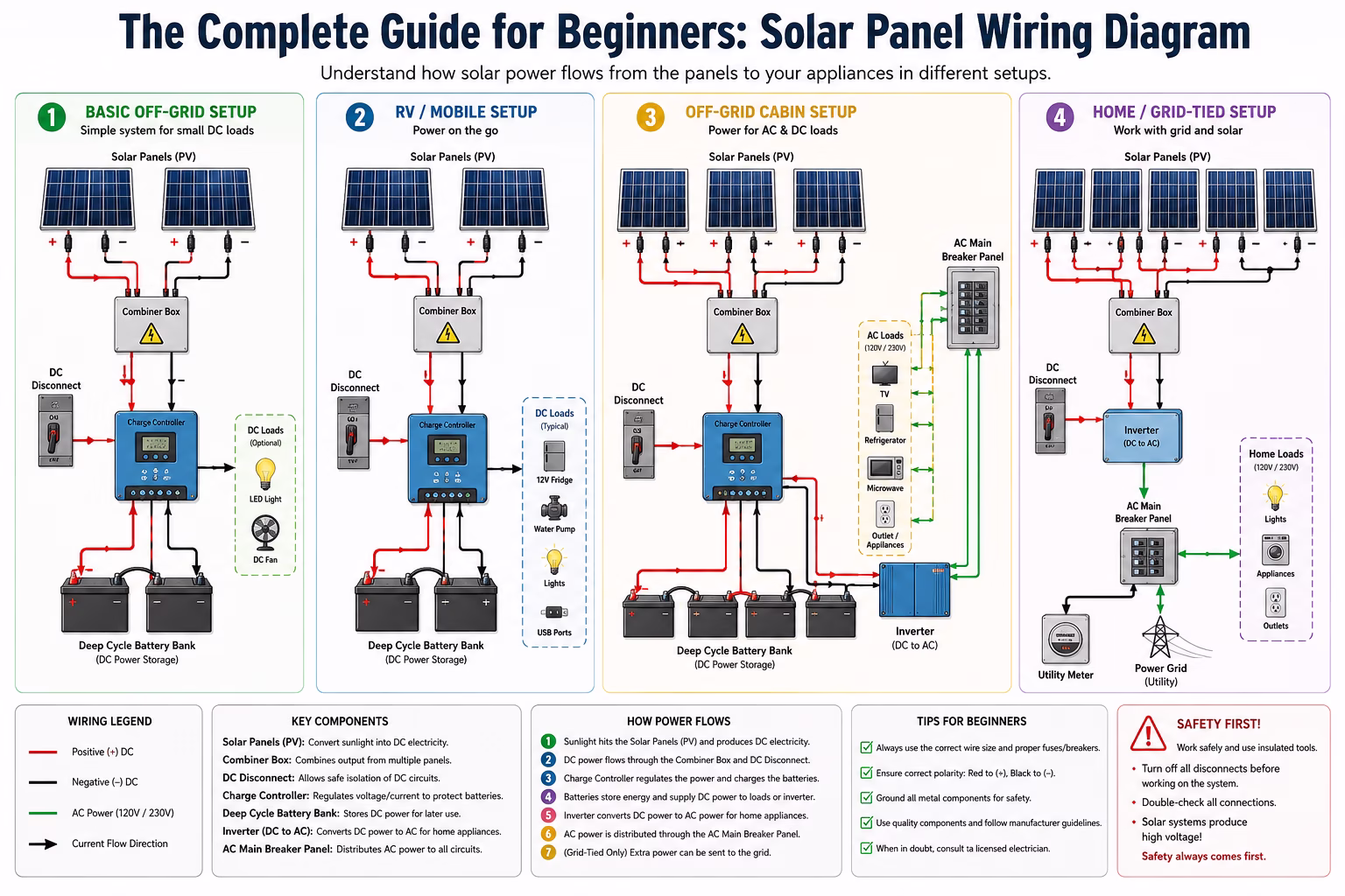
3. Core Components in Any Solar Circuit Setup
Before drawing a diagram, it helps to understand what goes into a solar electricity setup. Most systems, from a portable solar setup to a full rooftop solar installation, share the same basic building blocks.
Solar Panels
Solar panels are the heart of any solar energy system wiring plan. They capture sunlight and convert it into DC electricity through the photovoltaic effect. Each panel has a positive and a negative terminal. How those terminals connect to other panels determines whether the system runs at higher voltage or higher current.
Charge Controller
The charge controller sits between the solar panels and the battery bank. Its job is to regulate the voltage and current flowing into the batteries so they do not overcharge or get damaged. There are two main types: MPPT (Maximum Power Point Tracking) and PWM (Pulse Width Modulation). The choice between them affects how the panels should be wired.
Battery Bank
The battery bank stores energy for use when the panels are not producing power — at night or during cloudy weather. In a 12 volt solar wiring setup, batteries are typically connected in parallel to increase capacity. For a 24-volt system, batteries are connected in series to double the voltage.
Inverter
The inverter converts DC power from the batteries or panels into AC power that regular household appliances can use. In a solar panel wiring diagram without an inverter, only DC devices are powered directly from the battery or panels — common in small shed or cabin setups.
Fuses and Breakers
A solar fuse installation and proper solar breaker wiring protect the system against short circuits and overloads. Every run of wire that connects major components needs appropriate overcurrent protection. This is a non-negotiable part of any solar panel wiring diagram with fuse and breaker setup.
Combiner Box and Wiring
A solar combiner box brings together the outputs of multiple solar panels into a single output before sending power to the charge controller. It is commonly used in larger arrays. Proper solar wire gauge selection and attention to the dc wiring diagram ensure minimal energy loss.
4. Series vs. Parallel: Understanding the Two Solar Wiring Configurations
The single most important concept in solar panel connection diagrams is understanding series vs. parallel solar panels. Both configurations produce the same total wattage, but they differ in how voltage and current behave.
Connect Solar Panels in Series
- Positive terminal of one panel connects to negative of the next
- Adds up voltages while keeping current (amps) the same
- Example: Three 20V/5A panels → 60V at 5A
- Pairs with MPPT charge controller
- Preferred for 24V or 48V systems
- Best in unshaded conditions
Connect Solar Panels in Parallel
- All positive terminals connect together; all negatives together
- Adds up amps while keeping voltage the same
- Example: Three 20V/5A panels → 20V at 15A
- Suits 12 volt solar wiring systems
- One shaded panel doesn't affect the rest
- Best for beginners using PWM controllers
Series-Parallel Combination
For larger arrays, combining both methods gives the best of both worlds. Panels are grouped into series strings first, then those strings are connected in parallel. This approach balances voltage and current and is common in residential solar systems and grid-tie solar systems.
5. How to Wire 2 Solar Panels in Series & Parallel – Diagrams Explained
Learning how to wire 2 solar panels in series diagram is one of the first practical skills in DIY solar. The concept is straightforward:
- Connect the positive (+) terminal of Panel 1 to the negative (–) terminal of Panel 2
- The remaining positive of Panel 2 and the remaining negative of Panel 1 become the output leads
- These output leads connect to the input of the charge controller
In a typical how to wire 2 solar panels in series diagram, labels should clearly show the polarity at each connection point. Color coding helps — red for positive, black for negative — as it prevents mix-ups that could damage the controller or cause a short circuit.
This wiring method doubles the output voltage compared to a single panel. If each panel produces 20V, the combined output is 40V, which suits a 24V solar panel wiring diagram for beginners very well.
How to Wire Solar Panels in Parallel – Easy Diagram
For those asking how to wire solar panels in parallel diagram easy, the process is just as simple — but the result is different. Instead of chaining panels end-to-end, all positives join together and all negatives join together.
Using a solar combiner box makes this cleaner and safer. Each panel's output feeds into the combiner, which produces a single positive and single negative output to the charge controller.
Parallel wiring is the go-to method for a 12v solar system wiring diagram for beginners. It keeps the voltage low and predictable, making it compatible with budget-friendly PWM controllers.
Calculate How Many Solar Panels You Need
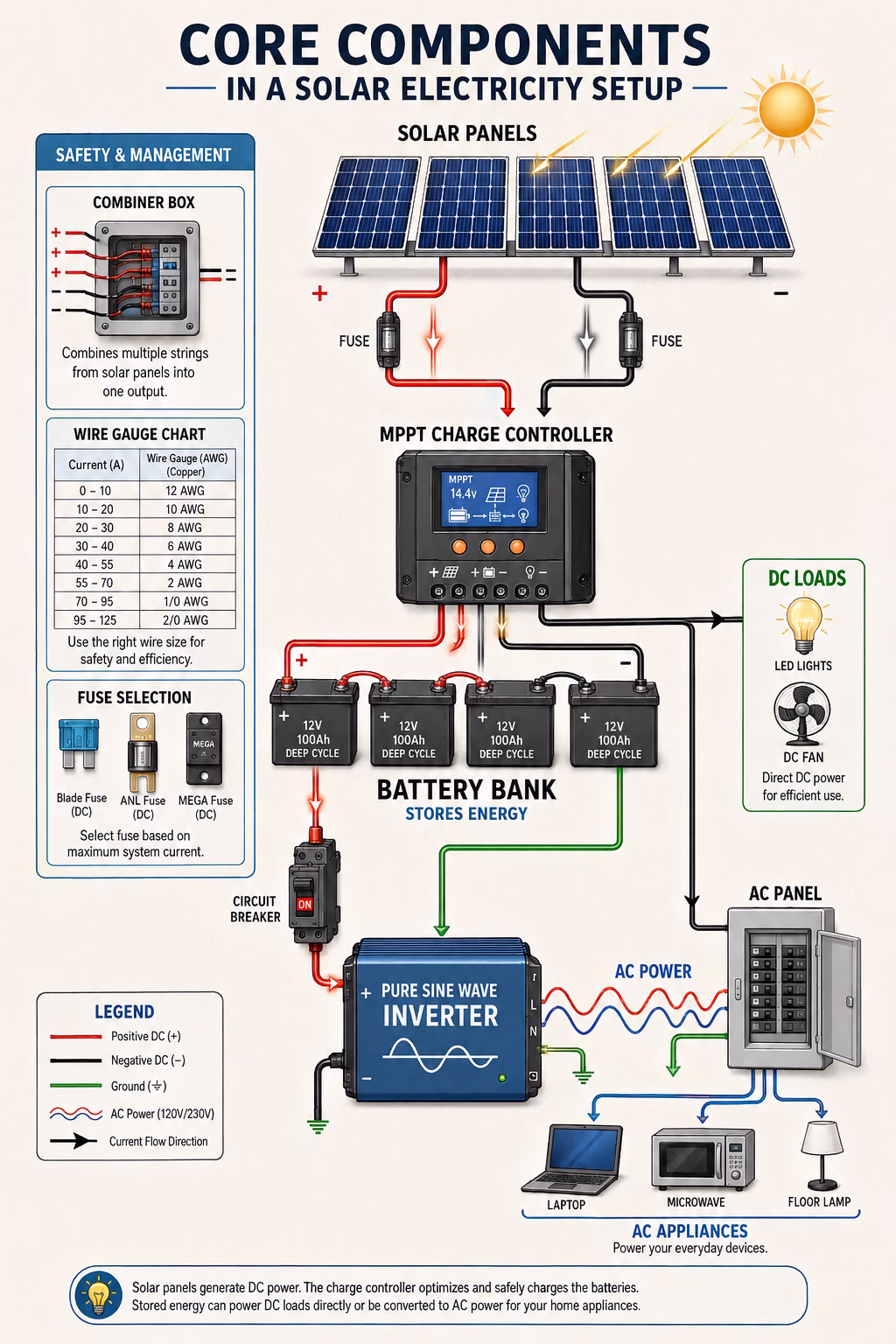
Use our free calculator to size your system correctly before wiring.6. 12V, 24V, and 48V Solar Panel Wiring Diagrams
12V Solar Panel Wiring Diagram with Battery and Inverter
A 12v solar panel wiring diagram with battery and inverter covers the most common solar setup found in sheds, small cabins, RVs, and budget home systems. Here is how the components connect:
- Solar panels (wired in parallel for 12V output) connect to the solar charge controller setup
- The charge controller connects to the 12V battery bank
- A solar inverter connection runs from the battery bank to the inverter (with inline fuse)
- The inverter connects to household outlets or appliances (AC loads)
- DC loads (12V lights, USB chargers) connect directly from the battery through a fuse
Fuses belong on every positive wire between major components. In a 12v solar panel wiring diagram with battery and inverter, the fuse between the battery and inverter is especially critical because the inverter draws very high current.
24V Solar Panel Wiring Diagram for Beginners
A 24v solar panel wiring diagram for beginners looks similar to the 12V version, but the voltage doubles throughout the system. This is useful for larger power loads or longer wire runs, where higher voltage reduces energy loss.
To achieve a 24V system, either:
- Use 24V panels (less common for small DIY setups)
- Wire two 12V panels in series (common and cost-effective)
- Wire two 12V batteries in series to create a 24V battery bank
A 24 volt solar system setup pairs naturally with a larger MPPT charge controller, since the higher panel voltage needs proper regulation before reaching the batteries.
48V Solar Battery Wiring for Larger Systems
A 48v solar battery wiring arrangement suits larger homes, backup power solar systems, and renewable energy setups that power heavy appliances like air conditioners, well pumps, or electric vehicle chargers.
To build a 48V battery bank from 12V batteries, four batteries are wired in series. Alternatively, four 12V battery pairs can each be wired in parallel first, then those pairs wired in series to reach 48V. Larger systems like these always benefit from a properly designed clean energy system diagram drawn before any physical wiring begins.
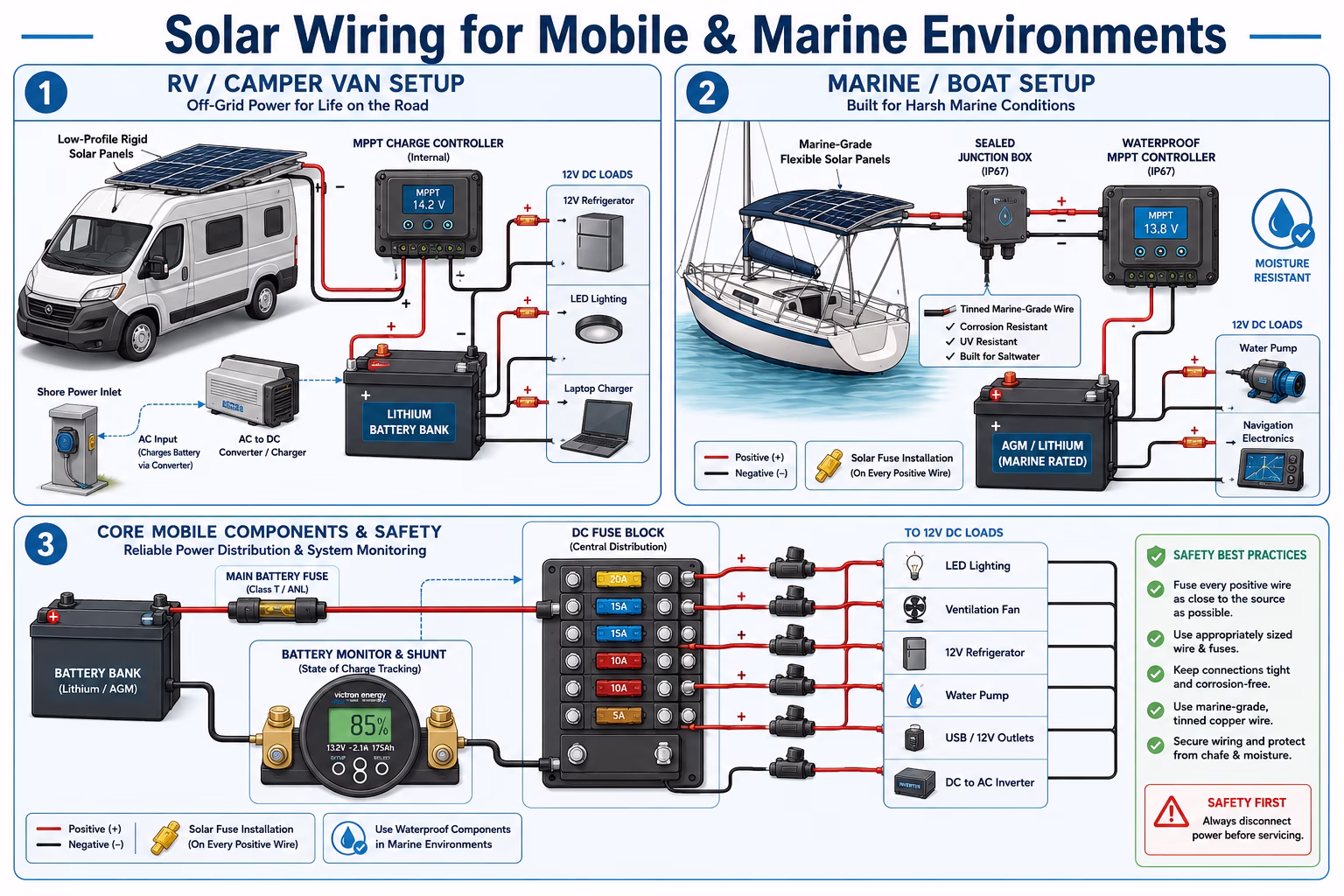
7. Off-Grid Solar Wiring: Shed, Cabin, and Tiny House Diagrams
Basic Off-Grid Solar Wiring Diagram Step by Step
A basic off grid solar wiring diagram step by step gives beginners a clear sequence to follow. Here is how a typical off-grid solar setup comes together:
- 1Mount the panels — Install the panels on the roof, ground mount, or portable frame. Run the panel cables to the location of the charge controller.
- 2Install the charge controller — Mount the charge controller near the battery bank. Keep the wire run between panels and controller as short as practical to minimize voltage drop.
- 3Connect the battery bank — Wire the batteries together (in series, parallel, or series-parallel depending on desired voltage). Connect the battery bank to the charge controller following the manufacturer's polarity markings.
- 4Connect the inverter — Run heavy-gauge cable from the battery bank to the inverter. Install a properly rated fuse within 18 inches of the battery positive terminal.
- 5Connect the loads — DC loads connect directly from the battery through a fuse or fuse box. AC loads connect through the inverter's output.
- 6Connect the panels to the controller — Finally, connect the solar panels to the charge controller's PV input terminals.
This sequence covers a standard off grid solar panel wiring diagram for beginners approach. Following it carefully avoids the common mistake of connecting panels before the controller is fully wired — which can damage the controller.
Solar Panel Wiring Diagram for Shed
A solar panel wiring diagram for shed is one of the simplest real-world applications. Sheds typically need just enough power for a few lights, a small power tool, or a phone charger. A common shed setup includes: 1 × 100W solar panel, 1 × 10A PWM charge controller, 1 × 100Ah 12V battery, 1 × small pure sine wave inverter (300–500W), and fused output for lights and outlets.
Solar Panel Wiring Diagram for Tiny House
A solar panel wiring diagram for tiny house must balance space constraints with real energy needs. Tiny houses typically need between 1,000W and 3,000W of solar capacity, depending on how the residents live. Recommended components include 4 to 8 × 200W–400W panels, an MPPT charge controller (40A–60A), a 24V or 48V lithium battery solar setup, and a 2,000W–3,000W pure sine wave inverter.
A lithium battery solar setup is increasingly popular for tiny houses because lithium batteries are lighter, cycle longer, and tolerate deeper discharges than lead-acid alternatives.
Solar Panel Wiring Diagram for Cabin Off Grid
A solar panel wiring diagram for cabin off grid shares many similarities with a tiny house setup. The key difference is that a cabin may be used seasonally, meaning the battery bank needs to sustain loads for longer periods without recharging. For a cabin off grid solar setup, consider a larger battery capacity (3–7 days of autonomy), a properly sized solar cable size calculator estimate to avoid thin wire causing power loss, and winterization provisions if the cabin is in a cold climate — lithium batteries handle cold better than flooded lead-acid.
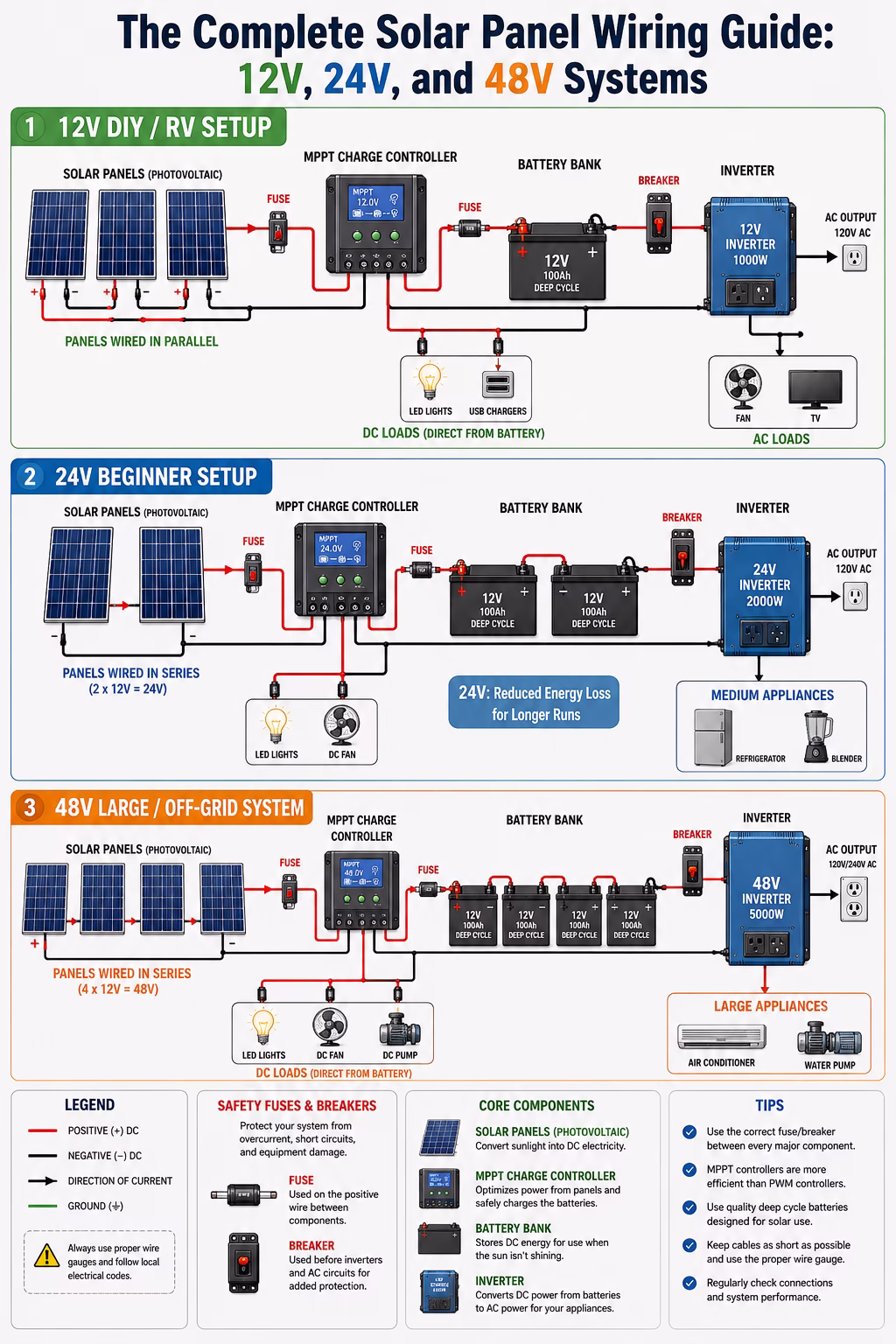
8. RV, Camper Van, and Marine Solar Panel Wiring
Solar Panel Wiring Diagram for RV Battery Setup
A solar panel wiring diagram for rv battery setup has a few unique considerations that a home setup does not. RVs already have a 12V DC system built in, which the solar setup integrates with. Key elements include roof-mounted panels (often flexible or low-profile rigid panels), an MPPT charge controller mounted inside the RV, integration with the existing 12V battery (or upgraded lithium battery bank), connection to the RV's inverter/charger or standalone inverter, and shore power plug integration for campground use. A solar fuse installation at every DC circuit is non-negotiable. Visit our RV solar calculator to size your system correctly.
Camper Solar Wiring and Van Life Solar System
Camper solar wiring and van life solar system setups are among the most popular DIY solar projects today. A well-designed van solar setup can comfortably run a 12V refrigerator, LED lighting, laptop charging, a water pump, and even a small diesel heater controller. A typical van life solar system includes 200W–600W of roof solar panels, a 20A–40A MPPT charge controller, 100Ah–200Ah lithium battery, 1,000W–2,000W inverter, fuse block for DC loads, and a battery monitor and shunt for tracking state of charge. See our mobile and marine solar guide for more details.
Marine Solar Panel Setup
A marine solar panel setup faces the most demanding conditions of any solar application — constant moisture, salt air, vibration, and limited mounting space. For boat owners, the key considerations are marine-rated solar panels with sealed junction boxes, waterproof MPPT or PWM controller, AGM or lithium batteries (flooded lead-acid is not ideal below deck due to hydrogen gas), tinned marine-grade wire (resists corrosion better than standard copper), and waterproof fuse holders and solar fuse installation throughout. The dc wiring diagram for a boat follows the same principles as any other solar battery connection, but every component must meet marine electrical standards.
9. Charge Controller Wiring: MPPT vs. PWM
Knowing how to connect solar panel to charge controller diagram is a foundational skill. The charge controller is the first thing that should receive panel power, and it should already be connected to the battery before the panels are plugged in.
Here is the correct connection sequence for a solar charge controller setup:
- Connect the battery to the controller first (battery terminal on controller)
- Then connect the DC load outputs (if using)
- Finally, connect the solar panels to the PV input on the controller
Reversing this sequence — connecting panels before batteries — can damage or destroy some charge controllers. Always read the manufacturer's sequence instructions.
MPPT Charge Controller Wiring
- Accepts wide range of input voltages
- Panels can be wired in series for higher voltage
- Best for systems 400W and above
- Ideal for 24V or 48V solar battery wiring
- Suited for cold climates (higher Voc in cold)
- More expensive but higher efficiency
PWM Controller Wiring
- Works best when panel voltage matches battery voltage
- Simpler and less expensive
- Best for small systems under 200W
- Ideal for 12V systems with parallel panels
- Good for basic shed or cabin setups
- Less efficient with big voltage differences
10. Battery Bank Wiring and Lithium Battery Solar Setup
When looking at how to wire solar panels to battery bank diagram, the key is that the charge controller sits between the panels and the bank — panels never connect directly to batteries without a controller.
Battery bank wiring itself depends on the voltage and capacity goals:
- 12V system: Wire all batteries in parallel (positive-to-positive, negative-to-negative)
- 24V system from 12V batteries: Wire two batteries in series; wire multiple series pairs in parallel
- 48V system from 12V batteries: Wire four batteries in series; wire multiple groups in parallel
Solar Panel Wiring Diagram for 2 Batteries
A solar panel wiring diagram for 2 batteries is one of the most common beginner setups. Two batteries can be wired in two ways:
- In Parallel (12V system, doubled capacity): Positive of Battery 1 connects to positive of Battery 2; Negative of Battery 1 connects to negative of Battery 2; output voltage remains 12V; capacity doubles.
- In Series (24V system, same capacity): Positive of Battery 1 connects to negative of Battery 2; the remaining negative of Battery 1 and positive of Battery 2 become the output terminals; output voltage doubles to 24V; capacity stays the same.
Lithium Battery Solar Setup Best Practices
Battery bank wiring is one area where careful planning pays off. A poorly wired battery bank with unequal wire lengths causes batteries to charge and discharge unevenly, shortening their lifespan. Best practices include using equal-length cables for all inter-battery connections and alternating where positive and negative outputs are taken from to ensure even current distribution.
A lithium battery solar setup has additional considerations. Most lithium batteries (especially LiFePO4) include an internal Battery Management System (BMS) that handles overcharge and over-discharge protection. They also tolerate deeper discharges than lead-acid and perform better in partial-state-of-charge conditions. For van life solar systems, tiny houses, and portable solar setups, lithium is increasingly the standard choice despite the higher upfront cost. Read our battery storage guide for a full comparison.
11. Hybrid Solar Inverter Wiring and Grid-Tie Systems
Hybrid Solar Inverter Wiring
Hybrid solar inverter wiring is for systems that connect both to a battery bank and to the utility grid. A hybrid inverter can charge batteries from solar panels, power loads from solar, batteries, or grid (automatically prioritising solar), export excess solar power back to the grid (where net metering is available), and provide backup power during grid outages — unlike a standard grid-tied inverter, which shuts down during outages.
The hybrid solar inverter wiring diagram is more complex than a basic off-grid setup because it includes both the DC battery connection and an AC connection to the main switchboard. A licensed electrician must handle the grid-connection side in most countries. For homeowners who want solar, battery backup, and grid connectivity, hybrid inverter wiring represents the most flexible solar energy system wiring option available.
Grid-Tie Solar System and Net Metering Connection
A grid tie solar system connects a home's solar panels directly to the utility grid without requiring a battery bank. Any excess solar power feeds back into the grid, and the homeowner receives credit for it through a net metering connection. Key components include solar panels (typically wired in series strings for high voltage), a string inverter, an AC disconnect and solar breaker wiring at the main panel, and a bidirectional electricity meter for net metering. A rooftop solar installation for a standard grid-tied residential solar system typically requires permits and inspection before it can be connected to the grid. Grid-tied systems do not work during blackouts unless a battery backup solar system is included. See our analysis on whether solar is worth it in 2026.
12. Rooftop Solar Installation and Residential Solar System
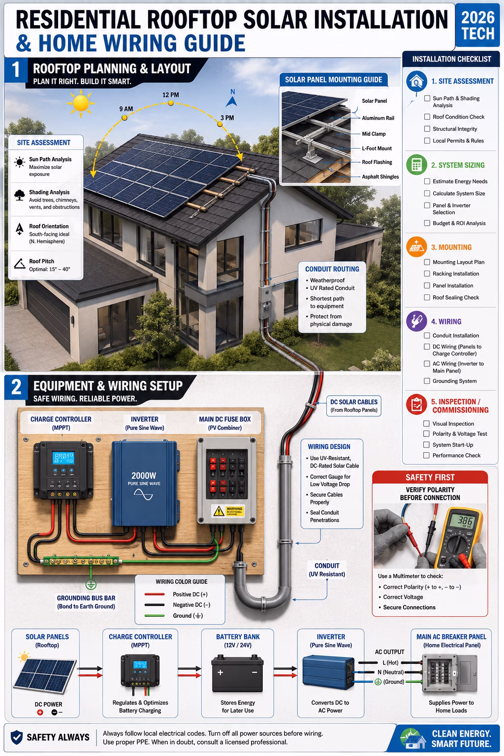
A rooftop solar installation for a full residential solar system involves more planning than a small DIY setup, but the core principles of the solar wiring setup remain the same. Key steps include:
- Site assessment — Check roof orientation, pitch, shading from trees or nearby structures, and structural capacity
- System sizing — Calculate household energy consumption and size panels and batteries accordingly
- Solar panel mounting guide — Choose the right racking system for the roof type (asphalt shingle, metal, flat/ballasted)
- Wiring design — Plan the photovoltaic wiring diagram, including combiner box location, conduit routing, and inverter placement
- Installation — Install panels, run conduit, connect combiner box, wire inverter, and connect to main panel
- Inspection and commissioning — Arrange for electrical inspection and utility interconnection approval
For most rooftop solar installations above 5kW, working with a certified solar installer is strongly recommended. Large systems involve high voltages and must meet local electrical codes. Use our solar panel cost guide for 2026 to understand the investment involved.
How to Install Solar Panel Wiring at Home – Overview
For those ready to tackle a small DIY how to install solar panel wiring at home project, the simplified overview is: mount the charge controller, inverter, and fuse box on a piece of plywood near the battery bank; run conduit or cable tray from the roof entry point to the equipment location; pull solar cable (DC-rated, UV-resistant outdoor cable) through the conduit; connect the charge controller to the battery bank first (positive then negative); connect the inverter to the battery bank with appropriately fused heavy cable; connect the solar panel output cable to the charge controller PV input; and test the system.
Always use a multimeter to verify polarity before making each connection. This simple step prevents most wiring mistakes in a DIY solar installation.
13. Solar Cable Size Calculator, Wire Gauge Chart, and Current Calculation
Choosing the right wire size is critical for safety and efficiency. Undersized wire causes voltage drop (wasting energy) and can overheat (causing fires).
| Current (Amps) | Recommended Wire Gauge (AWG) | Typical Use |
|---|---|---|
| Up to 15A | 14 AWG | Small panel to controller runs |
| 15–30A | 10–12 AWG | Controller to battery, small arrays |
| 30–60A | 6–8 AWG | Battery to inverter (small systems) |
| 60–100A | 2–4 AWG | Battery to inverter (large systems) |
| 100A+ | 1/0–4/0 AWG | High-capacity inverter connections |
Solar Current Calculation
To calculate the maximum current in any part of the system:
- Panel to controller current: Panel short-circuit current (Isc) × number of parallel strings
- Controller to battery current: Controller's maximum output current rating
- Battery to inverter current: Inverter wattage ÷ battery voltage (e.g., 3000W ÷ 24V = 125A)
Always size fuses and breakers at 125–150% of the expected maximum continuous current.
Solar Panel Wiring Diagram with Fuse and Breaker
A solar panel wiring diagram with fuse and breaker is the responsible way to design any system. Every positive wire between major components should have overcurrent protection — either a fuse or a breaker. Here is where fuses and breakers belong:
- Between battery and inverter: Largest fuse (sized to the inverter's max input current)
- Between battery and charge controller: Medium fuse (sized to the controller's max output)
- Between solar panels and charge controller: Fuse or breaker (sized to the max solar current)
- Between battery and DC load fuse box: Fuse at the battery end
- Each individual DC load: Fuse at the source
Estimate Your Solar System Cost
Use our detailed calculator for accurate 2026 pricing in your area.14. Solar Safety Guidelines and System Maintenance
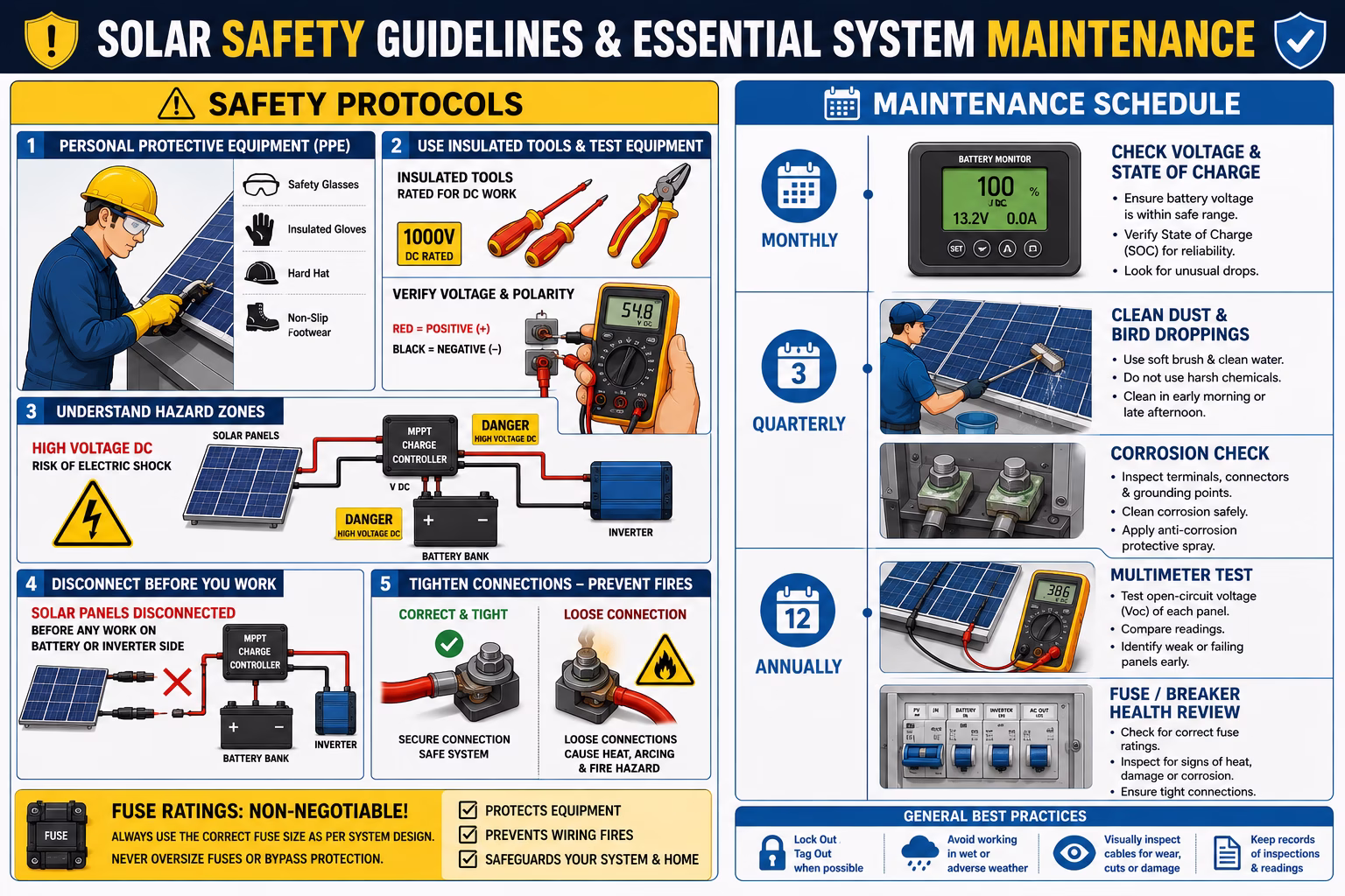
A solar energy system involves real electrical hazards, especially on the DC side where high current is present at all times whenever the sun shines. Following solar safety guidelines protects both the installer and the equipment.
- Always disconnect solar panels from the charge controller before working on the battery or inverter side
- Use insulated tools rated for DC electrical work
- Wear safety glasses when working near batteries (battery acid is hazardous)
- Label all wires clearly with voltage and polarity
- Never work alone on a system larger than a small portable setup
- Check wire connections for tightness — loose connections cause heat buildup and fires
- Use the correct fuse ratings — never substitute a higher-rated fuse to "solve" a tripping problem
Solar System Maintenance Schedule
Regular solar system maintenance keeps a system performing at its best:
- Monthly: Check battery voltage and state of charge; inspect visible wiring for damage
- Quarterly: Clean panels (dust and bird droppings reduce output significantly); check all connections for tightness and corrosion
- Annually: Test each panel's output with a multimeter; check battery health; review fuse and breaker condition
For a grid-tied system, the inverter's monitoring app (most modern inverters include one) makes it easy to spot performance drops that indicate a problem. Visit our guide on smart solar monitoring and IoT for more detail.
Solar Panel Wiring Diagram Explained for Beginners – Final Summary
After working through this entire solar wiring guide, the key takeaways come down to a few core principles:
- Plan before building. A solar panel wiring diagram explained for beginners always starts on paper. Draw it out, label everything, and verify before touching a single wire.
- Match your wiring to your charge controller. Series wiring for MPPT, parallel for PWM in a 12V system.
- Fuse everything. Every major connection needs overcurrent protection sized to the wire.
- Follow the correct connection sequence. Battery first, loads second, panels last.
- Use the right wire size. A solar wire gauge chart and solar cable size calculator are the beginner's best friends.
- Respect the DC side. Solar panels are live in sunlight and cannot be switched off — they demand respect at all times.
Whether someone is wiring a simple solar setup wiring diagram with battery for a weekend cabin, designing a full residential solar system, or building a van life solar system for the open road, the fundamentals are always the same. Get the diagram right, follow it carefully, and the renewable energy system will serve reliably for decades.
Frequently Asked Questions
Conclusion: Your Solar Panel Wiring Diagram Starting Point
The Bottom Line
A well-designed solar panel wiring diagram is the foundation of every successful solar installation — from a single-panel shed setup to a full residential system. The rules are the same at every scale: plan carefully, size your wire correctly, fuse every connection, follow the right connection sequence, and respect the DC side of the system.
Whether you are building a van life solar system, powering a cabin off grid, or installing a rooftop system on your home, the information in this guide gives you everything needed to approach the project with confidence.
The most important thing anyone can do before touching a wire is to draw the complete system diagram first — label every component, note every fuse rating, and confirm every connection before any physical installation begins. That single step is what separates successful DIY solar installers from those who have to start over after a mistake.