Complete Solar Wiring Diagram for RV, Van & Boat Systems with Battery Blueprint
Table of Contents
- 1. Introduction
- 2. Why DIY Setups Fail
- 3. What a 12V Wiring Diagram Looks Like
- 4. Core Components Every System Needs
- 5. Rooftop RV Solar Wiring
- 6. Solar Wiring for Van Conversion
- 7. How to Wire RV Solar from Scratch
- 8. Series vs Parallel Efficiency
- 9. Deep-Cycle Battery Connections
- 10. Inline Protection & Fuse Sizing
- 11. Inverter Wiring Diagram
- 12. Marine Solar Wiring Layout
- 13. Optimized Setup for Boondocking
- 14. Line-to-Line Wiring Breakdown
- 15. Universal 12V Wiring for Beginners
- 16. Troubleshooting Your Setup
- 17. RV vs Van vs Boat Differences
- 18. RV Solar Setup Cost Calculator
- 19. Real Installation Examples
- 20. Frequently Asked Questions
- 21. Final Notes from the Field
I've burned through more than my share of bad wiring setups over the years — melted terminals, undersized fuses, a battery bank that nearly caught fire in a Class C motorhome in the Arizona desert. Those mistakes are exactly why I put this guide together.
If you're setting up a solar wiring diagram for RV, van & boat systems from scratch — or fixing an existing mess — this is the step-by-step breakdown you actually need. No fluff. No guesswork. Just real wiring knowledge from years of hands-on installs.
Why Most DIY Solar Setups Fail Before They Start

Every week, someone in a van life forum posts a photo of their wiring and asks why the system isn't working. Nine times out of ten, the problem is the same: they skipped the planning phase.
The most common failures I see:
- Wire gauge too thin for the amperage load
- Fuses placed too far from the battery
- Charge controller wired backward or skipped entirely
- Batteries wired incorrectly (partial parallel, mismatched ages)
- No busbar — just daisy-chained connections off the battery terminals
The solar panels themselves are almost never the issue. The wiring is where everything breaks down.
What a 12V Solar Wiring Diagram for RV, Van & Boat Systems Actually Looks Like

Before you touch a single wire, you need to understand the full energy chain in a low-voltage 12V solar wiring diagram for RV, van & boat systems layout.
Here's how power flows from the sun to your devices:
And if you're running AC appliances:
Every component in that chain has a job. Miss one — or wire it wrong — and the whole system underperforms or fails.
Core Components Every System Needs

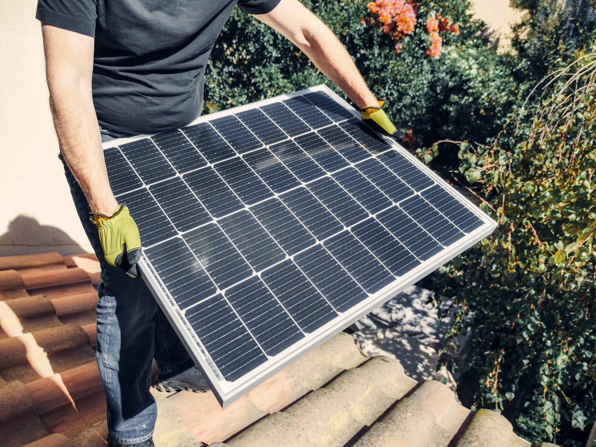
Solar Panels
You'll run either rigid monocrystalline panels or flexible ones depending on your roof situation. Rigid panels are more efficient and last longer. Flexible sun panels for curved roofs work great on vans and fiberglass boat decks, but they run hotter and degrade faster.
For a typical RV weekend setup, 200–400 watts of panels is a solid starting point. Full-time van lifers or boondockers usually need 400–800+ watts.
Solar Charge Controller
This is the brain between your panels and batteries. You have two types:
- PWM (Pulse Width Modulation): Cheaper, simpler, less efficient. Fine for small systems under 200W with matching panel and battery voltage.
- MPPT (Maximum Power Point Tracking): More expensive but extracts 20–30% more power from your panels. Required for any system over 200W or when panel voltage is significantly higher than battery voltage.
For PWM solar charge controller wiring, the connection sequence is always: battery first, then panels. Wiring panels first with no battery connected can fry the controller.
Battery Bank
Your choice here matters enormously. You have three main options:
- Flooded Lead-Acid (FLA): Cheap but heavy, needs ventilation, can only use 50% of capacity
- AGM (Absorbed Glass Mat): Maintenance-free, sealed, better depth of discharge — about 60%
- Lithium (LiFePO4): Most expensive upfront, but 80–100% usable capacity, longer lifespan, lighter weight
For any serious rv solar setup with batteries explained, lithium is the right long-term choice if you can swing the cost. See our Battery Storage Guide for a full comparison.
Inverter
An inverter converts 12V DC to 120V AC so you can run standard household appliances. For sensitive electronics like laptops, CPAP machines, or TVs, always use a pure sine wave rv solar inverter wiring diagram schematic — not a modified sine wave. Modified sine wave inverters are cheap but can damage or shorten the life of sensitive gear.
Fuse Block and Busbars
Every circuit needs overcurrent protection. A fuse block distributes power safely to individual loads. Positive and negative busbars centralize your connections and keep the wiring clean and serviceable.
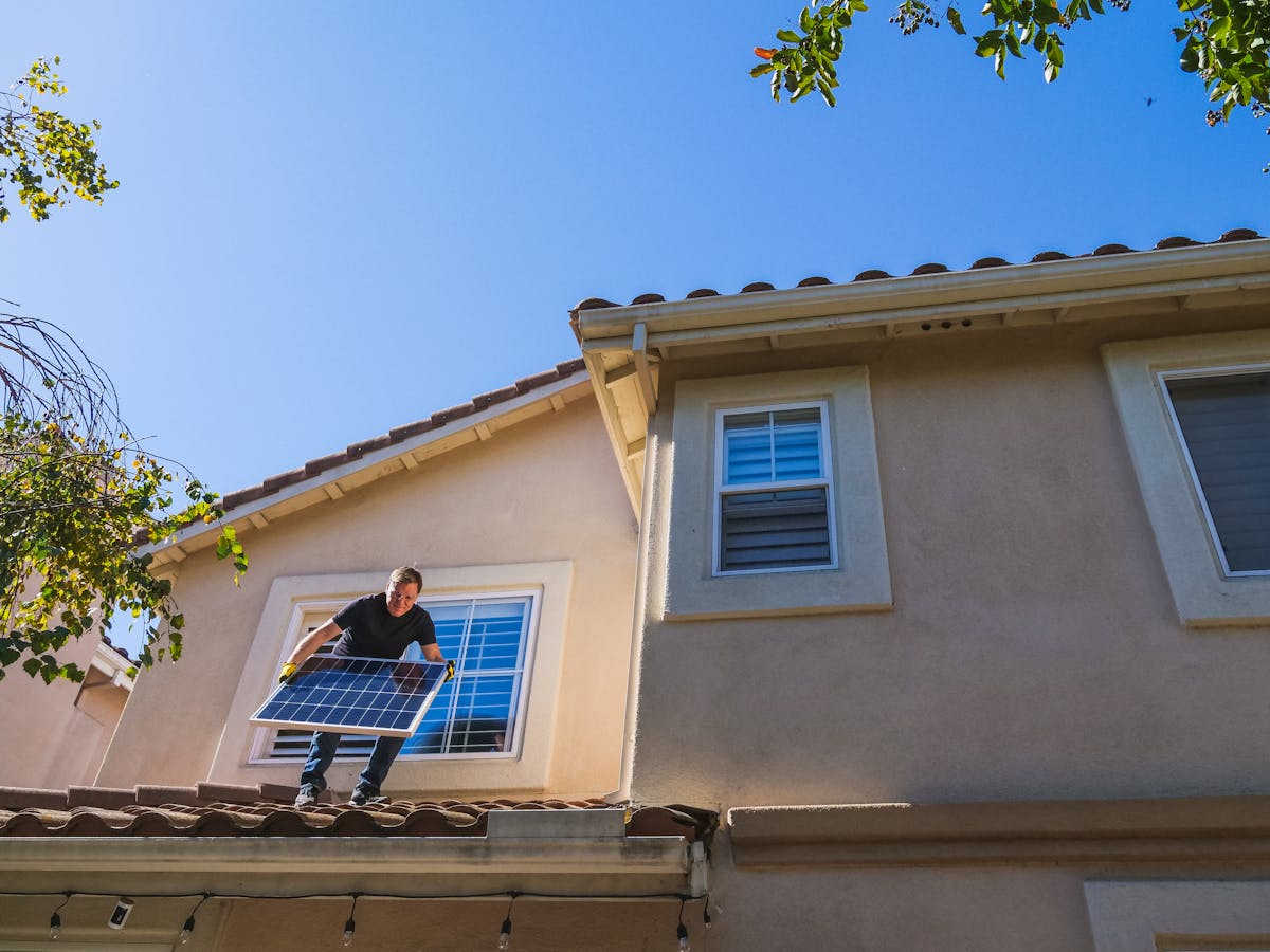
Rooftop RV Solar Panel Wiring Diagram Configuration

Mounting Solar Panels on RV Roofs
The mounting system matters as much as the panels themselves. Use corrosion-resistant aluminum Z-brackets or tilting mounts. Seal every penetration through the roof with self-leveling lap sealant — I use Dicor on most RV installs.
Route your panel wiring through a weatherproof cable entry gland, not a bare hole. A single cable entry gland can pass two or four wires and keeps rain out permanently.
Leave at least 3 inches of clearance under rigid panels for airflow. Panels cook without it, and heat kills efficiency fast.
Wire Gauge from Roof Panels to Controller
For rooftop panel wiring, most runs are 10–20 feet from the panels to the charge controller. Use at least 10 AWG wire for runs under 15 feet on a 20A circuit. For longer runs, step up to 8 AWG to keep voltage drop under 3%.
Use the voltage drop formula:
Don't eyeball this. Voltage drop on long rooftop runs robs real power from your system every single day.
Solar Panel Wiring Diagram for Van Conversion Projects

Stealth Van Solar Wiring Diagram with Alternator Charging
Van builds have unique requirements. Space is tight, the roof is often curved, and most van lifers want their system invisible from outside.
For a stealth van solar wiring diagram with alternator charging, you'll typically combine:
- Rooftop solar panels (flexible or low-profile rigid)
- Shore power input (optional, for campgrounds)
- Alternator charging via a DC-DC charger or battery isolator relay
A DC-DC charger (also called a battery-to-battery charger or B2B charger) is the right choice for charging lithium from your alternator. Simple isolator relays don't charge lithium properly and can strain your vehicle's charging system.
Compact Camper Solar Wiring Diagram with Inverter
For a cargo van or compact camper, a typical working system looks like:
- 2 × 200W panels on roof (series or parallel, depending on controller)
- 40A MPPT charge controller
- 200Ah lithium battery
- 2000W pure sine wave inverter
- 100A fuse on inverter cable
- 40A ANL fuse between battery and busbar
That setup comfortably runs a 12V fridge, lighting, phone/laptop charging, and occasional inverter use for 1–3 days without sun. For broader van and boat life planning, visit our Van & Boat Life Guide.
How to Wire RV Solar System from Scratch

Step 1: Size Your System First
Before buying anything, calculate your daily power consumption in watt-hours (Wh):
- Add up the wattage of every device you'll run
- Multiply each by hours per day of use
- Sum all watt-hours
- Divide by your battery's usable percentage (80% for lithium, 50% for lead-acid)
That gives you your minimum battery capacity. Size your panels to refill that in 4–5 hours of good sun. Use our RV Solar Calculator to get instant sizing estimates.
Step 2: Choose Your Charge Controller
If your panels and battery are the same voltage (e.g., 12V panels, 12V battery), PWM solar charge controller wiring works fine for small systems. The moment your panels exceed your battery voltage — which happens with any 24V or 36V panel string — you need MPPT.
For the charge controller diagram setup:
- Mount the controller in a ventilated area, not in a sealed box
- Wire battery terminals first (positive, then negative)
- Wire PV input from panels (positive, then negative)
- Wire load output to fuse block if using the controller's load terminals
Step 3: Wire the Battery Bank
Whether you're running 12V, 24V, or 48V, your battery bank has to be wired correctly for balanced charging and discharging.
Solar Panel Series vs Parallel Efficiency — Which Is Better?

This is one of the most misunderstood topics in DIY solar. Let me make it simple.
Series Wiring
In series, you connect the positive terminal of one panel to the negative terminal of the next. This adds voltage but keeps amperage the same.
Use series when:
- Your charge controller requires higher input voltage (most MPPT controllers work best at 2–3× battery voltage)
- You have long wire runs (higher voltage = lower current = less voltage drop)
- Panels are identical in specs
Downside: If one panel gets partially shaded, it drags down the whole string.
Parallel Wiring
In parallel, positives connect to positives, negatives to negatives. This adds amperage but keeps voltage the same.
Use parallel when:
- Your panels are wired to a PWM controller matched to battery voltage
- Partial shading is a concern — one shaded panel doesn't kill the others
- You need to stay within a controller's voltage limit
How to Connect Solar Panels Serial or Parallel Safely
For most RV and van systems with MPPT controllers, a series-parallel combination delivers the best results. Wire pairs of panels in series, then wire those series strings in parallel.
This approach is common in a series-parallel 12v solar battery wiring diagram matrix for larger builds. For a broader US solar sizing overview, see our Solar Calculator USA.
Deep-Cycle RV Battery Solar Wiring Diagram Connections

How to Wire RV Batteries in Parallel
For the parallel method: how to connect 12v solar panels and batteries correctly, here's the critical rule: always use equal-length cables from each battery to the busbar.
Unequal cable lengths create unequal resistance. That means batteries charge and discharge unevenly, which shortens their lifespan and creates hotspots.
Tutorial on how to wire 12V solar batteries in parallel:
- Place batteries side by side
- Connect all negative terminals together with equal-length cables to the negative busbar
- Connect all positive terminals together with equal-length cables to the positive busbar
- Fuse each positive cable within 12 inches of the battery terminal
- Connect the charge controller's battery output and the inverter to the busbars — NOT directly to individual battery terminals
Wiring Batteries in Series (for 24V or 48V Systems)
For 24V systems, connect the negative terminal of Battery 1 to the positive terminal of Battery 2. Your system's main positive comes off Battery 2's positive; main negative off Battery 1's negative.
Lithium-Based RV Solar Battery Setup Management
Lithium batteries require a Battery Management System (BMS). Most quality lithium batteries have an integrated BMS, but verify it handles your inverter's surge current. A 2000W inverter draws up to 200A at peak — your BMS needs to handle that without shutting down.
Li-ion solar charge controller settings differ from lead-acid. Set your MPPT charge parameters to:
- Absorption voltage: 14.4V (12V system)
- Float voltage: 13.6V
- Low voltage cutoff: 12.0V
Never use a lead-acid charge profile on lithium. It will overcharge and damage the cells. Learn more in our Battery Storage Guide.
Inline Protection: 12V Solar Fuse Wiring Diagram Calculator

Fuses protect the wire, not the device. Fuse sizing is based on the wire's ampacity — not the device's draw.
Fuse Placement Rules
- Between battery and inverter: Fuse within 18 inches of the battery positive terminal
- Between battery and charge controller: Fuse within 12 inches of battery
- Between battery and fuse block: Fuse within 12 inches of battery
- Between each panel and combiner box: Include a string fuse for each parallel string exceeding 2 strings
| Wire Gauge | Max Ampacity | Recommended Fuse Size |
|---|---|---|
| 14 AWG | 15A | 15A |
| 12 AWG | 20A | 20A |
| 10 AWG | 30A | 30A |
| 8 AWG | 40–50A | 40A |
| 6 AWG | 55–65A | 60A |
| 4 AWG | 85A | 80A |
| 2 AWG | 115A | 100–110A |
| 1/0 AWG | 150A | 150A |
| 2/0 AWG | 175A | 175A |
| 4/0 AWG | 230A | 200–225A |
For an ANL fuse on an inverter cable, always size for the wire, not for the inverter's rated output. For cost planning, see our Solar Panel Cost 2026 guide.
Pure Sine Wave RV Solar Inverter Wiring Diagram Schematic

Inverter Placement and Cable Sizing
The inverter should mount within 18–24 inches of the battery bank. Every additional foot of cable adds resistance — and inverter cables carry massive current.
For a 2000W inverter on a 12V system: 2000W ÷ 12V = 167A. In practice, with inefficiency and surge, you're looking at 200A+ momentarily. Use 2/0 AWG or 4/0 AWG cable for runs under 36 inches.
High-Power RV Solar Inverter Setup Calibrations
After installation, configure the inverter's low-voltage cutoff. Set it above your battery's minimum safe voltage:
- Lithium: 11.5–12.0V cutoff
- Lead-acid/AGM: 11.8–12.2V cutoff
This prevents the inverter from draining batteries into damage territory during overnight use.
RV Solar Setup with Inverter Charger
An inverter-charger combines the inverter and a shore power charger in one unit. Brands like Victron MultiPlus, Renogy, and Xantrex make popular units for this integrated rv solar setup with inverter charger approach.
When shore power is available, the inverter-charger passes it through to your loads and simultaneously charges the battery. When shore power cuts out, it seamlessly switches to battery power. For full-timers, this is the right architecture.
Waterproof Boat Solar Panel Wiring Diagram Layout

Marine Grade Boat Solar System Wiring Diagram Blueprint
Marine environments are brutal on solar equipment. Salt air corrodes connections in weeks if you use standard hardware. Build your marine solar system with:
- Tinned copper wire — not bare copper, which corrodes rapidly in saltwater air
- Marine-grade ring terminals — heat-shrink adhesive-lined, not plain crimp
- 316 stainless steel fasteners — not zinc-plated, which rusts fast
- Sealed waterproof fuse holders — rated for marine environments
- UV-resistant conduit — for any exposed wire runs on deck
Corrosion-free 12V marine solar wiring standards aren't optional — they're the difference between a system that lasts a decade and one that fails in a season.
Weatherproof Marine Solar Panels for Saltwater
Select panels with an IP67 or IP68 rating for any boat installation. For high-output solar panels for boats and yachts, look at flexible panels for curved decks and rigid panels with anodized aluminum frames rated for salt exposure.
Grounding on Boats
Marine solar systems require careful grounding. On a fiberglass boat, create a dedicated DC grounding point — don't use the engine block or the AC ground as your DC negative reference. Improper grounding on a boat can cause galvanic corrosion that eats through metal through-hulls and fittings.
Optimized Best RV Solar Wiring Setup for Boondocking
Off-Grid RV Solar Wiring Diagram with Battery Bank
Boondocking — camping without hookups — demands a self-sufficient, robust system. The rv solar setup for boondocking needs a battery bank large enough to carry you through 2–3 cloudy days.
A practical standalone off-grid RV solar wiring diagram template for a large RV:
- 800W solar array (4 × 200W panels, wired 2S2P)
- 60A MPPT charge controller
- 400Ah lithium battery bank (2 × 200Ah in parallel)
- 3000W pure sine wave inverter-charger
- 200A ANL fuse on battery positive
- 40A DC-DC charger for alternator backup
- Shore power inlet (30A or 50A depending on RV)
This setup supports full appliance loads — residential fridge, microwave occasional use, rooftop AC (marginal with this setup), CPAP, lighting, entertainment, phone charging. For off-grid cabin sizing, also see our Solar Calculator for Off Grid Cabin.
RV Solar Setup for Full Time Living Requirements
Full-timing demands the best rv solar setup for full-timers. You're not weekending — you need reliability 365 days a year. Key considerations:
- Redundancy: Have at least two methods of charging (solar + alternator, or solar + shore power hookup)
- Overcapacity: Size your battery bank 30–50% larger than calculations suggest
- Monitoring: Install a battery monitor (Victron SmartShunt or similar) so you always know your state of charge
- Wire quality: Don't use automotive wire for your main runs. Use marine-grade tinned copper for anything in the battery compartment
Track your system's performance with Smart Monitoring Solutions.
Line-to-Line RV Solar Setup Wiring Diagram Breakdown

Here's how a complete, real-world wiring layout flows from component to component:
This automotive style 12v rv solar wiring harness approach keeps the main power runs short, keeps fuses close to the battery, and makes the system fully serviceable.
Universal 12V Solar Wiring Diagram for Beginners

If you're new to all of this, here's the beginner-friendly simple rv solar wiring diagram schematic that I recommend to first-timers.
Portable 12V Solar Setup Wiring Diagram with Fuses
Start small. A 100W beginner system teaches you how everything works without risking a full build:
Components:
- 1 × 100W 12V panel
- 1 × 20A PWM charge controller
- 1 × 100Ah AGM battery
- 1 × 30A inline fuse (between controller and battery)
- 1 × 10A inline blade fuse per load
Direct terminal 12V solar panel to battery wiring steps:
- Mount the charge controller
- Run battery cables — positive through a 30A fuse — to the controller's battery terminals
- Run panel wires to the controller's solar input terminals
- Connect your loads to the controller's load output or directly to the battery through a fuse block
- Verify polarity on everything before connecting the panel
That's your DIY guide to 12v solar panel wiring connections — simple, safe, and reversible.
Troubleshooting Your RV Solar Setup

Low Voltage Problems
If your batteries aren't reaching full charge:
- Check solar input voltage at the charge controller display — it should be significantly above battery voltage when panels are in sun
- Check for loose MC4 connectors on the panel strings
- Verify your charge controller absorption voltage is set correctly
- Check for shading — even a shadow across 10% of a panel dramatically cuts output
Batteries Draining Overnight
If your batteries are dying when no one is using power:
- Use a clamp meter to check for parasitic draws on individual circuits
- Verify your inverter isn't idling — 99% of inverters draw 0.5–2A even at zero load
- Check that your charge controller's load terminals don't have anything always-on drawing power
Fuse Keeps Blowing
If a fuse blows repeatedly:
- The wire is undersized for the load — upgrade wire gauge
- There's a short somewhere in the circuit — inspect every connection point
- The load itself has failed and is drawing excessive current — disconnect and test the load separately
For ongoing maintenance best practices, see our Solar Maintenance Guide.
RV vs Van vs Boat: Key Wiring Differences

| Feature | RV | Van | Boat |
|---|---|---|---|
| Panel mounting | Rigid on flat roof | Flexible or low-profile rigid | Flexible or marine-rated rigid |
| Wire type | Standard copper | Standard copper | Tinned marine-grade copper |
| Grounding | Chassis ground OK | Chassis ground OK | Dedicated DC ground bus only |
| Alternator charging | Via isolator or DC-DC | Via DC-DC charger | Via alternator with marine regulator |
| Waterproofing | Basic weatherproofing | Basic weatherproofing | Full IP67+ marine sealing |
| Shore power | 30A or 50A RV pedestal | 15–30A campground | Shore power pedestal with marine inlet |
RV Solar Setup Cost Calculator Basics

Rough costs for a mid-tier 400W, 200Ah lithium system (materials only):
| Component | Approx. Cost |
|---|---|
| 4 × 100W panels | $250–$400 |
| 40A MPPT charge controller | $150–$300 |
| 200Ah lithium battery | $600–$900 |
| 2000W inverter-charger | $300–$800 |
| Wiring, fuses, busbars | $100–$200 |
| Cable entry, connectors, mounts | $50–$100 |
| Total | $1,450–$2,700 |
Prices vary significantly by brand and quality tier. Don't cut corners on wire, fuses, and connectors — that's where fires start. For monthly savings projections, use our Monthly Savings Calculator.
Real Installation Examples

Weekend Warrior RV: 400W Setup
A couple using a 30-foot fifth wheel for weekend and holiday trips needs a simpler setup. Their load analysis: 12V fridge (40Ah/day), LED lights (5Ah/day), phone charging (5Ah/day), fan (10Ah/day) = 60Ah/day.
Setup: 2 × 200W panels in series → 30A MPPT → 100Ah lithium → 1000W inverter for occasional TV use.
Total material cost: ~$1,200. Install time: one weekend.
Full-Time Van Lifer: 600W Stealth Build
A remote worker living and working from a Transit cargo van needs reliable power for a laptop, monitor, lighting, 12V fridge, and occasional cooking appliance.
Load: 150Ah/day. Setup: 3 × 200W flexible panels in a 2S1P + 1P configuration → 60A MPPT → 300Ah lithium → 2000W pure sine inverter → DC-DC charger for alternator backup.
This is a textbook solar wiring diagram for camper van build — stealth exterior, reliable power, full workstation capability.
Sailboat: 320W Marine System
A 40-foot cruising sailboat needs to power navigation instruments, autopilot, refrigeration, lighting, and communications. Load: 100–120Ah/day.
Setup: 4 × 80W marine-grade panels in two 2S strings in parallel → 30A MPPT → 200Ah AGM battery bank → 2000W pure sine inverter → marine-grade wiring throughout.
Critical add: a battery monitor and a solar monitor on the chart table so the crew always knows power state. This is the marine grade boat solar system wiring diagram blueprint that keeps a cruising boat self-sufficient offshore.
After hundreds of installs across RVs, vans, and boats, the biggest lesson I can share is this: plan for twice the battery capacity and half the loads you think you'll need. Solar energy is abundant but not unlimited — and the difference between a frustrating system and a liberating one is almost always battery size and wire quality.
Use real marine-grade tinned wire for anything near water. Use MPPT controllers for anything over 200W. Use lithium if your budget allows. Fuse everything close to the source. And test your system before you leave on a trip — not when you're three days into the desert.
The rv solar wiring kit specifications, fuse charts, and wiring layouts in this guide give you everything you need to build a system that works on day one and keeps working for years.
Do it right the first time. Your future self — parked somewhere beautiful with full batteries — will thank you.
Ready to Size Your RV, Van or Boat Solar System?
Don't guess your power needs. Use our professional solar calculator to get exact panel and battery requirements for your mobile or marine setup — built for real-world off-grid conditions.
📊 Run Solar Panel CalculatorFast • Accurate • 100% Free to Use
Frequently Asked Questions
How do you wire solar panels in an RV?
Run panel cables from the roof through a weatherproof cable entry gland to your MPPT or PWM charge controller. Connect panels to the PV input terminals, then connect the controller's battery terminals to your house battery bank through an appropriately sized fuse. From the battery, run a fused positive cable to a 12V fuse block for your loads.
Should RV solar panels be wired in series or parallel?
It depends on your charge controller. MPPT controllers handle higher voltage input efficiently, making series or series-parallel wiring ideal. PWM controllers require your panel voltage to match your battery voltage, so parallel is safer for those. Most modern RV setups use MPPT with panels wired in series.
How do I connect solar panels to RV batteries safely?
Always fuse the positive wire within 12 inches of the battery terminal. Use appropriately sized wire (10 AWG minimum for most systems). Never connect panels directly to batteries without a charge controller — unregulated charging destroys batteries fast.
What size wire should I use for a 12V RV solar system?
For panel-to-controller runs under 15 feet on a 20A circuit, use 10 AWG. For battery-to-inverter runs, use 2/0 AWG or 4/0 AWG depending on inverter size. For fuse block circuits, use 12–14 AWG per circuit. Always size wire for the maximum continuous current, then add a fuse sized for the wire — not the load.
Can I run an RV completely on solar power?
Yes, but it requires adequate panel wattage, sufficient battery capacity, and a clear understanding of your daily energy consumption. Full-timers running rooftop AC will find solar alone insufficient — you need 1000+ watts of panels and 400Ah+ of lithium just for modest AC use. For everything except rooftop AC, a well-designed 400–800W system handles a full-time RV lifestyle comfortably.
What fuse size should I use in RV solar wiring?
Fuse for the wire, not the load. 10 AWG wire gets a 30A fuse. 8 AWG gets a 40–50A fuse. 4 AWG gets an 80A fuse. Your inverter cable fuse is sized for the wire gauge used, placed within 18 inches of the battery positive terminal.
How do marine solar wiring systems differ from RV systems?
Marine systems require tinned copper wire, marine-rated fuse holders, and corrosion-resistant hardware throughout. Grounding must be isolated from the AC grounding system to prevent galvanic corrosion. All connections should be sealed with adhesive heat-shrink terminals or covered in dielectric grease. Saltwater environments destroy standard automotive and RV hardware in months.
What is the safest way to wire a camper solar setup?
Plan the full layout before buying materials. Fuse every circuit as close to the positive battery terminal as possible. Use wire rated for at least 125% of your circuit's maximum continuous load. Connect and disconnect in the correct order (battery first when connecting, panels first when disconnecting). Label every circuit. Use a busbar system rather than stacking multiple ring terminals on battery posts.
How many batteries do I need for off-grid RV solar?
Calculate your daily consumption in amp-hours, then multiply by the number of days of reserve you want (typically 2–3 days). Divide that by your battery's usable capacity percentage (80% for lithium, 50% for lead-acid). That gives your total amp-hour requirement.
This article covers the complete solar wiring diagram for RV van & boat systems, including battery banks, inverters, charge controllers, fuse sizing, marine wiring standards, and series vs parallel panel wiring. Always consult a licensed electrician for systems above 48V or for any grid-tied installation. See our Engineering Disclaimer and Privacy Policy for more information.